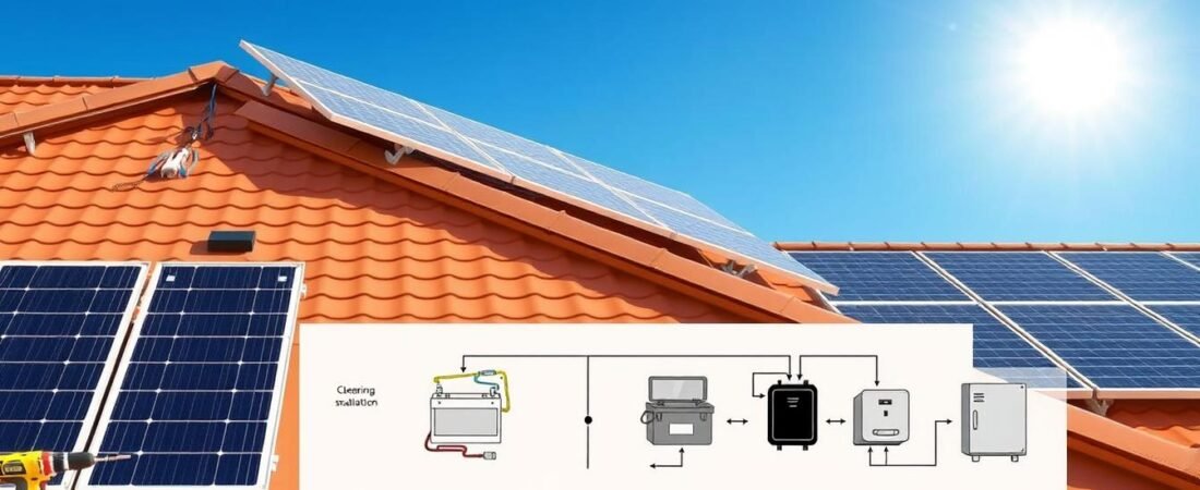
Start smart: this short guide helps you read a clear solar panel installation diagram and plan a safe home system. Learn the basics of wiring, battery care, and inverter placement so your setup runs well.
Many homeowners use an all-in-one unit like the EcoFlow DELTA Pro 3, which keeps key components in a single portable box. That simplifies connections and reduces gear clutter.
Tip: sizing your array, checking roof orientation, and avoiding shading will boost electricity output over time. Review voltage and circuit needs before you connect any devices.
Money note: professional installations often qualify for the 30% Federal Solar Tax Credit, which can cut total cost significantly.
This guide gives a basic example of wiring and equipment choices so you can ask smart questions and plan with confidence.
Understanding the Solar Panel Installation Diagram
A clear wiring map shows how each module links to your inverter and battery so the whole system runs safely.
What it is: A diagram is a graphic map of connections between panels, charge controllers, batteries, and inverters. It shows how strings or series connections affect voltage and overall power.
Why it matters: Visualizing your solar panel wiring prevents reversed polarity and incorrect voltage that can ruin components. Good documentation also guides roof layout and circuit routing.
- Ensures correct voltage and safe wire sizing.
- Clarifies where each component and connection sits in the array.
- Makes troubleshooting and future upgrades simpler.
“Always verify that the schematic matches your specific equipment before you make any final connections.”
| Wiring Type | Effect on Voltage | Typical Use |
|---|---|---|
| Series (string) | Increases voltage, same current | Long runs to match inverter input |
| Parallel | Increases current, same voltage | Keep voltage within battery limits |
| Hybrid | Mix of voltage and current control | Large arrays with multiple inverters |
Why Accurate Schematics Matter for Your System
A reliable schematic turns complex wiring into a clear path for safe, long-lasting power at home.
Good planning reduces guesswork and protects expensive equipment. Accurate drawings show where each panel, inverter, battery, and charge controller connects.
The National Electrical Code (NEC) caps many residential arrays at 600V, so a correct schematic helps you verify voltage limits before any work begins.
The Role of Planning
Start by mapping roof sections and potential shading. This step lets you place panels to maximize energy and avoid hot spots.
Use the schematic to confirm series and string layouts match inverter start-voltage and current ratings. That prevents underperformance and protects batteries and other components.
- Save time: installers follow a clear guide instead of improvising on the roof.
- Stay compliant: a proper plan helps meet NEC limits and local codes.
- Future-proof: documented wiring makes upgrades and maintenance simpler.
“Measure twice and cut once applies to wiring—accurate schematics prevent costly mistakes.”
Essential Components for a Functional Solar Array
A well-chosen set of components makes a rooftop energy system reliable and easy to maintain.
Core Hardware
Standard equipment includes high-quality solar panels, a reliable inverter, a battery or battery bank, and a charge controller to manage incoming voltage.
You’ll need a fuse box and breakers to protect equipment from overcurrent and short circuits. Always match panel voltage and current to the inverter’s DC input specs.
Cabling and Connectors
Use PV wire or solar cable and MC4 connectors for weather-resistant interconnections. Proper panel wiring and correct wire gauge keep power loss low over long runs.
Good wire management—clips or zip ties—keeps wiring tidy and prevents abrasion on the roof.
- Charge controllers regulate voltage before it hits the batteries.
- Choose cables rated for outdoor use and the array’s maximum voltage and current.
- Confirm all components work together by checking manufacturer specs for the inverter, battery, and panels.
“Select durable components and plan connections before final assembly to avoid costly rework.”
Comparing Series and Parallel Wiring Configurations
Choosing the right wiring layout directly affects how much electricity your array delivers each day.
Wiring panels in series raises total voltage while keeping current steady. That makes series strings useful when the inverter needs higher input voltage. Remember: the string voltage equals the sum of each panel’s output.
Parallel connections boost current and keep voltage the same. This setup helps when shading hits one module, because each unit works more independently. For roofs with mixed shade, parallel runs often keep steady energy all day.
Many pros combine both in a hybrid layout. Hybrid arrays balance voltage and amperage to match inverter limits and handle partial shading. Always confirm that your chosen configuration does not exceed the inverter’s maximum voltage or current ratings.
- Series: higher voltage, same current — good for long runs.
- Parallel: higher current, same voltage — good for shaded roofs.
- Hybrid: blends strings to optimize performance and reliability.
“Match wiring choices to inverter specs to protect equipment and maximize output.”
Designing Your Own Solar Panel Installation Diagram
Begin with a simple paper mockup and mark shade, roof pitch, and wiring runs before moving to digital tools.
Choosing a Medium
Paper works great for first drafts. It’s fast and flexible when you test layouts or string groupings.
Digital tools like Canva or Photoshop help create a neat example that you can share with an installer.
Determining Orientation
Note roof direction, pitch, and any shading. Those factors decide whether you choose series or parallel strings.
Tip: real-world sunlight and shading matter more than Standard Test Conditions when you size an array.
Drawing Connections
Label every connection from panels to the charge controller, battery, and inverter. Clear labels prevent costly errors.
Plan wire runs to minimize voltage drop and keep circuits tidy. Good wire management makes troubleshooting faster.
“Sketch first, then test the layout against inverter voltage and string size to ensure peak performance.”
| Step | What to Include | Why it Matters |
|---|---|---|
| Medium | Paper sketch or digital mockup | Easy edits and clear sharing |
| Orientation | Roof pitch, azimuth, shading | Optimizes energy and string choice |
| Connections | Label inverter, charge controller, batteries | Prevents wiring mistakes and boosts performance |
Navigating Inverter Options for Your Setup
Choosing the right inverter shapes how much usable electricity your rooftop array delivers each day.
The main choices are string inverters and microinverters. String inverters convert the combined DC output of many panels into AC for your home. They are mature and cost-effective when panels share similar sunlight and orientation.
Microinverters attach at each panel and let every module run at its own maximum power point. This is ideal for complex roofs with varying shade. One failed device won’t drag down the whole array.
Check specs: ensure any inverter can handle the total power and does not exceed its maximum DC input voltage. For string setups, keep panels in a string the same orientation to protect performance and voltage limits.
- String: cost-effective for uniform arrays.
- Microinverters: per-module optimization, better for shading.
For a practical guide to matching inverters and wiring, see how to build a solar inverter.
“The inverter is the heart of your system, converting DC into usable AC for home devices.”
Safety Protocols and Regulatory Compliance
Working near high-voltage arrays demands strict habits and clear checks before touching any live conductor. Safety protects people and costly equipment alike.
Managing High Voltage Risks
Start with verification. Always confirm a circuit is de-energized with a calibrated meter and lockout/tagout procedures. Treat exposed conductors as live until you verify zero volts.
Follow codes. Ensure the entire system meets local building codes and the National Electrical Code. Inspectors expect a clear wiring diagram and labeled connections to approve permits.
Use the right tools. Insulated tools, rated gloves, and outdoor-rated connectors cut the chance of shock or arc faults. Keep replacement fuses and breakers sized to the array’s current and voltage.
- High-voltage series strings increase risk; handle string wiring with care.
- Run software checks (for example, Aurora) to validate inverter and voltage limits.
- Include circuit protection—fuses, breakers, and rapid shutdown—to prevent fire and equipment damage.
“When in doubt, stop and consult a licensed electrician or installer; safety and code compliance are not optional.”
| Risk | Mitigation | Regulatory Check |
|---|---|---|
| High string voltage | Use insulated tools, follow lockout/tagout | Confirm NEC voltage limits |
| Incorrect connections | Label every conductor and tighten rated connectors | Provide wiring diagram for inspector |
| Overcurrent events | Install proper fuses and breakers | Match circuit protection to equipment specs |
When to Hire a Professional Installer
For larger arrays or jobs that tie into your home breaker box, professional help is often the smartest move. A licensed installer will ensure the work meets local codes and that your system safely integrates with existing circuits.
Pros bring tools and experience to size your system, place panels across complex roof planes, and plan panel wiring to avoid shading losses. They also match inverter and battery connections so voltage and power limits are respected.
Hiring an expert usually speeds permitting and inspection, which saves time and reduces risk. It can also shorten your payback period by optimizing energy output and preventing costly rework.
- Best for large or roof-complex projects that need electrical integration.
- Required when tying new equipment into your home circuit board.
- Pros handle permits, inspections, and code compliance.
- They size the array and wire runs to protect inverter and batteries.
“Investing in a licensed installer buys safety, code compliance, and often a faster return on your equipment.”
Final Thoughts on Solar System Success
Finish strong by checking connections, testing voltage, and confirming labels before you energize the array.
Double-check wiring paths and run a brief commissioning test to verify the inverter and breakers respond as expected.
Understand the basics: keep string voltages within device limits and match conductors to current to avoid heat and loss.
If you have any questions about your specific setup, consult a licensed pro to confirm panel layouts and final wiring choices.
Regular maintenance and simple monitoring boost power output and extend system life. Record baseline readings for future comparisons.
For a practical reference on PV design and builder guidance, see PV basics for builders. Enjoy the benefits of clean energy as your panels keep reducing home energy costs.